I'll never make any money as a blogger. Its never my goal or objective mind you, but it's abundantly clear to me that I could never make a living as a writer. I just don't do it consistently enough. These posts are mostly to gather and record my thoughts so I can remember later in life.
So I used NeoPixels to light my Christmas tree a 2022. I put a post up about it when I was getting started and never followed up. A lot like my photography posts. Oh well. The original post:
So I started to get it working quite well and had the tree wired up for the season. I never went on to build the web front end so I could change the lights remotely. Maybe in a future try.
I even had enough lights left over to wire the tree in our office:
In both cases I'm running the color wheel code example from the MIT project. I did make some that did alternate pattersn - like alternating red and green, sparkle/flashes, even did some hand mapping to do it by rows. All the code is in my XmasTreeLights github repo. In general it would be better to start with the Matt Parker code, the MIT code or AdaFruit's neopixel tutorials.
For last christmas, on a whim I decided to print a BBr2 (BaByR2) from a patreon I subscribe to: Michael Baddeley (I'm also printing a full size R2, more on that in another post).
So I sold all my camera gear and used the money to buy a BambuLabs P1S with AMS filament changer. It is an excellent printer. If you can afford one, get one. Even the P1P would be a great printer to get. Speed and quality in a single package that isn't "Prusa" expensive.
The body came out great on the first try.
The dome prints very well without supports.
Printed two legs, some tires and a center foot and it was time to assemble.
It's a very easy print and pretty easy to assemble with some screws and superglue. It takes 3 servo motors and somethign to control them. Since this was my first attempt I went simple with a FlySky FS-I6 from amazon.
I initially printed the oversized "cartoonish" dome. I just picked the default dome from the file list. After gluing and assembling I wired it up to an adafruit crickit to test the dome. Adafruit makes it super easy to control servos, especially when you're just testing things out.
I later found the holiday themed dome. I had some red filament laying around from a previous project idea so it seems a perfect time to test out the AMS. Turned out excellent! I bought some "metalic" paint markers from a craft store and started coloring the white in.
*EDIT/UPDATE* - found the time lapse footage for the Santa hat print:
The AMS does create a lot of waste with the filament changes however:
Later I went back and printed a classic dome in gray PLA and colored it in (still have some more to do)
Super fun project, glad I spent the time on it. Wish I had better hand/eye coordination to paint it better.
The single feather requires a lot less room than the stacked feather and prop maker feather wing. I was able to re-use the blade and neopixel strip from the first build. So I only had to get the prop maker rp2040 and the speaker.
It worked pretty good straight away
The odd lighting at the end of the saber is from the code not being configured with the right pixel count.
So our Cricut Maker hit the same rubber roller problem that everyone else who seems to own one of these hits eventually. If you google around for it you can see how often this occurs. Basically the material the rollers are made of deteriorates and starts to come out of the slots etched in the roller and gets pinched in the casing. It also will prevent the cutter mat from feeding correctly.
New rollers are easy enough to acquire. You can 3d print them in TPU or buy them from Amazon. Installing them is the tricky part. There are a bunch of Youtube videos on how to do it so I won't write my own. The trick is the first set of screws. There is a plate on the hinge of the cover plate that needs to be pried off so you can remove the screws. The issue is it seems they glue this piece in place now, making it all-but impossible to service this machine.
I was able to pry it off enough to get the screws out but there are now hairline cracks in the bracket. I used super glue to add some amount of strength to the cracked surface and am hoping for the best. The unit does cut now correctly so that part was a success.
It's really unfortunate that the Cricut company has made these units so unserviceable. They could have done a lot to make the device repairable. The closed software ecosystem is also a major drawback to this device. I think if I had the purchase to do all over again I'd probably go with a Brother unit or some other non-closed system.
This all started with the video by Matt Parker from @standupmaths He had a super cool Christmas Tree lights idea: I wired my tree with 500 LED lights and calculated their 3D coordinates.Pretty much like it sounds, he put neopixels on his tree and figured out a way to calculate their array position in 3d space. Kind of like stringing a measuring tape on your tree and knowing where every inch is relative to each other when looking at a single side. He then made a way for people to upload their own animations to his tree (I'll be skipping that part).
Anyway this is my hack at the same idea stealing everything from Mr Parker and the MIT students who helped him. Check out the links in his video description for more details. It's pretty neat, both the math of it and the execution.
So here's what I used:
First, I'm using the same lights that Matt linked to in his video. (affiliate links because Amazon has a handy tool bar to make short URLs) https://amzn.to/3AcK3yj - ALITOVE WS2811 RGB LED Pixels Light Individually Addressable 12mm Diffused Digital Full Color LED
I already had a Raspberry Pi 3 laying around:
rwhiffen@raspberrypi:~/prog/XmasTreeLights $ more /sys/firmware/devicetree/base/model
Raspberry Pi 3 Model B Rev 1.2
rwhiffen@raspberrypi:~/prog/XmasTreeLights $
I boought this 10A 5v power supply that came up as a *Products related to this item* suggestion. https://amzn.to/3g0u67x - Aclorol 5V 10A 50W Power Supply 100V-240V AC to DC Adapter 5V 10 amp Switching Converter 5.5x2.1mm Plug for WS2811 WS2812B WS2813 5V LED Strip Pixel Lights
The other stuff I had lying around from other projects, like gator clips with breadboard pins etc.
Here's a few of links that taught me how to do this. Sites that I mimicked the results of may be a better description than this post.
* There were a bunch of other pages I referenced while trying to debug what was going wrong with my setup.
This did not start out well. Initially I couldn't get the pixes to light up correctly.
First - most the LEDs wouldn't light up. Second the colors were off and they'd flicker and blink oddly. I had also incorrectly wired the pins at some point - now I'm not sure if I fried something. There are 10 of these 50-light strings so tired another one - same results.
Colors were still wrong, but it works. First up - to fix the colors I had to set the pixel_order parameter when creating the new strip in the code. If you read the @StandUpMaths code you'll see a comment about these particular strips be GreenRedBlue - GRB instead of RGB The example code I was using had this line:
And that got the strips working, so now I knew it was something with my Raspberry Pi not the lights. A little more searching and I discovered a post where someone mentioned moving off of the default GPIO 18 pin and onto 21 - so I set:
pixel_pin = board.D21
and it's started working! I can address each pixel and do the expected neopixel operations!
Next I wired up five of the 50-pixel strings and hit my next snag - the 10Amp power supply I have isn't quite enough to light all the pixels. So it's back to Amazon for a bigger power supply (and 500 more LEDs while I'm at it).
The funny thing is this list doesn't include the audio amplifier you need later in the guide. Oh well.
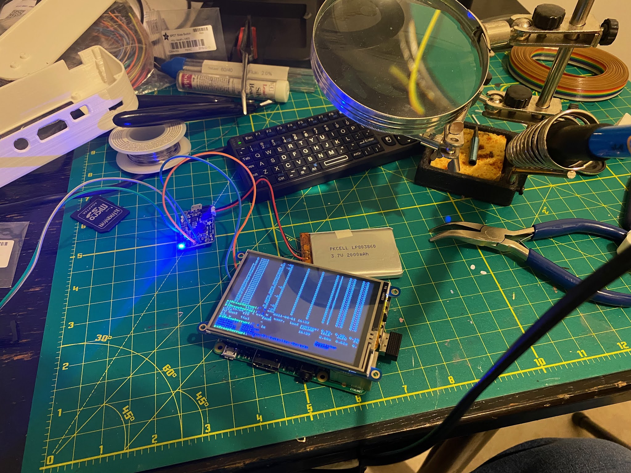
The STL's printed from my PrusaMini as is. Getting software working and parts connected turned out to pretty easy. Not simple mind you, but if you follow the steps, it goes pretty well.
The screw holes aren't sized very well, they're a bit too big. - I used my 3d former pen to fill in the holes and then drilled them to the right size.
Took a few tries to get the adafruit software to work the way I wanted it to, but eventually
But it works pretty well. Takes a while to get used to typing on the small screen. I don't think I have the eye sight needed to run the gui so I won't even try but it's a nifty little toy.
I'm catching up on my tinkering projects. The latest one: Kitty Toe Bean Keypad with Color TFT. I forgot to take in-progress pictures but here's the final just before assembly shots. I 3d printed the parts on my Prusa Mini and they came out excellent. Only some minor looseness in the snap-together parts. The rest of the parts I ordered from Adafruit.com listed in the build guide.
Pretty happy with how the qtPy soldering turned out
The Kahil Jade switch wiring isn't great, but it works - you have to solder to a pin/post which requires very steady hands to keep it smooth - I do not have steady hands.
Press fit together. You can see some of my sloppy soldering on the TFT display.
With the Toe Beans installed.
Here's a video of it in action - the original build guild has a dancing parrot as the image, I swapped out pictures of my cat Lola. Sorry about the vertical filming I wasn't paying attention.
All in all a fun project - the buttons do CMD+S (save), CMD+X (cut), CMD+C (copy) and CMD+P (paste). I'll have to open a thread in the adafruit forums as the overall performance is really slow. I have to hold the button longer than I would expect for it to take the action. In the video on the build guide you get the impression that it works much faster/smoother than that. Probably a wiring issue on my part
Ok so I was cleaning out my shelf and found a 3d pen I had from a while back. I think I got it on Woot.com or something like that for super cheap. They go on clearance at places like Michaels and JoAnn craft stores as well. Amazon sells a bunch and recommends this one. Mine is similar, but I don't think it's manufactured anymore.
So what I didn't realize when I bought it is it uses the same filament as my 3d printer. It makes total sense now, but I didn't connect the dots at the time. I put my 3d printer filament in it and it extruded great! which gave me another idea - could I use it to repair, weld or fill a 3d print.
The short answer is YES! I took two calibration cubes from my 'stuff I printed but is totally useless' box and tried to weld them together. It worked pretty good! I would need a lot of practice to get it smooth and neat, but it does work. I also filled in the X, Y and Z recessed letters to see how that would go and just like the weld, I need to practice and I think go slower - my pen has a variable feed rate to help this. I think it'll come in handy for some very specific use cases.
Anyway if you have a 3d print that you want to melt a little more filament onto for repair or aesthetic reasons, these 3d printing pens are a fun and relatively cheap way to go.
I don't tinker as much as I'd like. I usually get distracted surfing the web or playing Civ 6 games. Finally got around to trying to build one of these:
So it's super easy, requires no soldering (as the project title suggests) and turns out pretty cool.
Anyway finally got one in. I burned out one of my bluefruits in the process. I wired it upside down *AND* used a 12v power supply by mistake. YIKES! Smoked it right up. Going to have to buy another to replace it.
Side-note the crayon containers from Micheals (or JoAnn or the other craft stores) are fantastic for storing these things (you can see some on my messy desk)
So we got some snow here. The forecast projected it's arrival with pretty good accuracy. Since I had the advance warning, I set up a system to do a time lapse of it.
First thing was to find a camera that could run for 48 hours or more. Looking through my bin of parts and found my old iPhone 4s. Took a while to get it running 9.2 (not sure that was a wise choice). This version of iOS is pretty sluggish on an older iPhone. There's something to the class action lawsuit being filed.
Next up, I needed to find an app to take the photos. Luckily there's no shortage of apps in the app store to do this. The app Lapse It was free, and well reviewed. So I got it installed and it was amazingly easy to use.
Tap on New Capture:
I tapped on the timer and set it to take a photo every 15 minutes.
I took the defaults for everything else. You can only do 480p in the free version, to upgrade to 720p or 1080p you have to purchase the pro version. A fair tradeoff. Next I had to position the camera. I went low-tech:
We hadn't done much with LightStrike for a few months. It had pretty much turned into a NERF battleground here instead. I was modding out my nerf guns with voltage upgrades and upgrade kits from Orange Mod Works. Then out of nowhere, I hear that familiar sound of a LightStrike Gun turn on from one of the cubes outside my office. It quickly escalated into an impromptu battle in the office.
While I was on vacation I got an interesting comment posted and a google+ comment. The post comment from Michael Kröhnert on my first light strike mod post is about replacing some blown capacitors on a non-functional gun, interesting read, check it out if your into the internals of the guns. And Bernd Kammerer wants to try and make a Light Strike compatible gun. So I'm trying to reply to those today and probably fire up my guns again and start another skirmish.
Ok, I've been playing around a little bit more with my D.C.R.-012. Basically it's turned into my practice gun. I'm trying all my hacks and mods on this LightStrike gun first to learn my mistakes in one sand box as it were. At any rate, this time I decided to put a SPST push-button-style switch in. It turned out great functionally. Turned out horrific visually. First I decided to cut the clipping bracket off the back. I decided to take my new Dremel 4000 out for a spin on this mod, so I used a cutting disk to cut the piece off.
And then used a sanding band disk and buffing paste and felt pad. Lesson learned: Don't do that. Basically the plastic is far too soft to dremel at most speeds. You basically end up melting the plastic. Further I nicked the plastic where the headphone jack goes making it look even worse. Anyway, I finished up the job with a Xacto knife, which is what I should have started with. I cut a notch in each half of the case to fit the round button. Lesson #2, it's pretty hard to get this even, so either cut it out with the gun screwed back together, or put it on one side or the other, not along the lateral line.
I cut the lead going to the weapon select and soldered it to my push button. Interesting note about the capacitance sensing of the guns, they don't look for a specific value, but a delta in that value. If, for instance, you want to take a gator clip and temporarily clip a switch on, you have to do it while the gun is off. Otherwise it interprets the change in capacitance as having the button pressed and it cycles through the weapon settings continuously (which makes sense, I've increased the electron holding capacity of the wire lead. Cutting the copper tape off and putting the button on changed the initial value of the capacitance on startup but that initial value isn't important, it's changes in that value. Ok, here's what I considered the interesting part. The switch itself isn't enough. You have to put a wire lead hanging off the other end of the switch to hit the threshold needed to evoke the change. I tried some simple test and basically I need at least 3 inches of the wire I was using to get it to flip. To ensure it would trip. I used a red piece of solid core wire that's hard to see in my picture, but I basically just coiled it up in the dead space between the trigger housing and reload switch.
The End result, I have a button on the back of the gun that is now weapons select.
So now I can change weapons with one hand. I've got to tidy up the fit and finish a bit, there's gap still where the two halves meet and I cut too much on one side and will need to patch/bondo that back. But it works. I think the next switch I want to add is something like these two switch types:
These are both pictures from the radioshack.com website. The toggle with safety cover would look the coolest, but it's not a SPST. The 2nd switch is a SPST and it's lighted, so presumably you could add some more cool lights to the gun over all with this one. Anyway, we'll see if I actually get around to it. I had also thought it would be cool to have the weapon select button be a rotary switch, but as LYNX pointed out in his comment, rotary switches aren't typically SPST. I guess I could make Cam with a lobe on it to push a SPST button, but that'd be too much effort for me at this point. In the photos above, you can also see my 'learning' attempts with Amaco's Rub 'N Buff product line. I didn't prime the gun first, I simply started smearing it on, and it seemed to work as expected. The copper looks like it will give me the look I want. The silver leaf (not show) didn't work out as well as I had hoped. My local A.C. Moore only had those two colors, but now that I know how they look/work I feel a bit more comfortable about buying them online. I'll probably go for Ruby and Spanish Copper. Most of what I'm figuring out I've learned/read in various NERF gun mod sites and forums.
Still have a lot more practicing to do. It'll be interesting to see if this gun even functions by the time I'm done with it.
I've taked a few times about 'decoding the bits' so I thought I would finally get around to putting up a spreadsheet for anyone to see. A quick refresher of how I'm counting/tracking the output from the light strike devices: 65 'signals' come from the device. They come in two types: Pulses or Spaces. This is what the LIRC software refers to them as, so I just continue that. If it's wrong, it's GIGO from LIRC to me to you. The first signal is a large pulse, typically double the value of all other pulses you will get. This is the 'frame start' if you want to think of it in terms of a networking packet. The next 64 'bits' of information are alternating pulses and spaces. The pulses are constant. They're the markers between spaces to let you know when a space starts and ends. Since the pulses are simply borders for your spaces, you are left with 32 bits of data in your frame. Because I cheat and take the output from one of the LIRC utilities rather than reading the pulses directly, I count the pulses and spaces together for 64 'bits' in my coding (mostly because when I started I wasn't 100% sure if the pulses might have a hidden significance). So when you view the spreadsheet, even numbers are the spaces, odds are the pulses.
Here is the google docs spreadsheet of my light strike bit decodes. There are four tabs, one for the rifles, one for the pistols, one for the ITS and bit math where convert the bits from binary to base10 numbers to see the relative values. The pistols sheet is a work in progress, I only took one stab at decoding the only pistol anyone in my group has. It had surprising results. A laser strike from a pistol is different than the laser strike from the rifle. It makes sense in a way. The rifle bits add up to the number 1344, but the laser strike on the pistol is only 258 it seems. They seem drastically different which means I should probably revalidate the values coming out of the pistol.
I'll probably create a code.google.com project to dump my simple perl code into at some point too, with the hopes that someone who is an actual developer can take it further.
So I got around to taking apart my Light Strike scope. I didn't like that my gun was black but the scope is brown. I also didn't like how it looked or the plastic used to simulate the optics of a scope.
Other than enabling the two shot types for your gun, it wasn't that appealing to me over all and I doubted I would ever actually use it. So I decided to break it open. Break is the operative word here. Even after you remove the numerous screws hiding under the stickers (six of them I think) the scope doesn't come apart easily. The front plastic lens housing is essentially melted/glued in place. So you would not be able to take apart your scope and put it back together. I was thinking it might be fun to put a real laser pointer inside or some thing to act like a reflex sight to make it look cooler. No such luck.
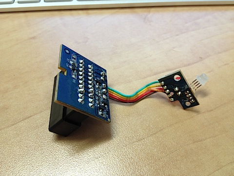
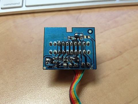
There really isn't much to the scope. It doesn't actively do anything other than flash the LEDs and enable the fire modes in software. I'm guessing some transistors and capacitors or resistors. I don't know how to tell the difference between SMD capacitors and SMD resistors. They have numbers like 101, 470 and other such values on them. The transistors have numbers too but I can't read them (they have three solder points so I'm guessing they're transistors). From there its a ribbon cable to the multicolor LED and red LED. The multicolor is the one that lights up the plastic dome on the top of the scope with your team color. The red one simply makes the red dot appear in the center of the rear optic.
So it would be quite simple to replace those two with something else like a real laser pointer. I took a laser pointer from a trade show apart and extracted just the laser goodies out of it, so if I can find something cool the mount it in, I will likely take the red LED out and replace it with a laser pointer.
Here's a closer view of the PCB.
Another interesting thing I found out: the ports are not interchangeable. You cannot plug the scope into the launcher/rapid fire port. The gun shuts down if you do. So my theory that the ports were a parallel bus before is wrong. Thankfully the gun doesn't fry if you plug it in backwards or in the wrong port. Anyway, there yo have it, the internals of the scope. I might decide to take apart the rapid fire system to see what's inside there as well.
All right! It's light strike mod time! I've decided to hack my D.C.R.-012 and do some mods to it. After you remove the stickers (which is a little too easy, the adhesive isn't very good) it looks like this:
The little copper patches are the 'switches' from the stickers. They are capacitance sensor based, which is neat and disappointing at the same time, because it make putting a real switch there complicated. Anyway, on one side there are a boat load of screws that need to be removed and the orange end-cap on the barrel needs to be taken off (comes off easy). After that, you see something like this:
Picture is a bit blurry, but you get the idea.
The 'brains' are interesting. Everything is clearly labeled in english for what it does. Things like CAP_SENSOR, LIFE, RELOAD or IR_RX so drastic mods would be pretty easy. The mount points for the attachments seem to be in parallel so they're likely only restricted by the plastic mount shape rather than the actual location. It would be interesting to see what would happen if you grafted a 3rd mount point on. Could you activate the tracker at the same time as the scope and launcher attachments?
Looking at the IR blaster (the opaque lens) and receiver (the black circle with the silver X on it)
The IR transmitter with the cone and lens removed.
I'm not doing much today, just changing some LED colors. the life bars are 3 red LEDs. Going to make them 3 different colors (well, specifically changing two reds out)
unscrewed them and soldered in a green and blue that I took out of some of my kids toys (sssshhh, don't tell! They were broken anyway). I would have rather done green -> yellow -> red but none of the toys had any yellow LEDs. I guess I could have gone white and then put a yellow film, but I'm just screwing around so what the heck.
First off, this Point-and-shoot camera stinks. Second, here's the two new LEDs in place. They're rounded on the top and the originals were flat, so I get a different light distribution in my new LEDs that isn't ideal. But it does work:
So now when I get hit, I lose blue -> green -> Red health bars. Some future mods I think I might do:
Move the on-off switch to where the head phone jack is. The headphone jack location would allow me to turn it on and off one handed while gripping the gun.
Try to get a mechanical switch to work with any of the buttons. In particular, weapon select would be neat to make into some kind of rotary or dial type button. A toggle switch for single fire/semi-auto fire, etc.
Graft on some 'extra bits' to give the gun more profile relief. I can't for the life of me figure out why they made all these guns so flat. I have some plastic tubing and other ornaments I could put on the sides with some LEDs to spruce up the side profile.
Paint job. I've been stalking the Nerf Modding forums looking for tips and pointers for how to paint plastic guns. So far I have a few ideas. I'll probably just go with basic silver and red to match the grip plastics
Next I take apart my scope and rapid fire attachments.
Ok, spent 10 minutes after lunch looking into the ITS signals.
You'll have to read the previous post about bits, to know what I'm rambling about, but in essence the significant bits were the even bits between 40 and 62. Not all are used, but I haven't tried all the guns and option combinations yet. So the ITS (Intelligent Targeting System) has 3 modes. Sentry mode - you have to hit the target 5 times, each time you hit it, you light up a bar with your team color. Fifth hit turns it into a sentry for your color. It blasts out random shots until it's captured by another team. Bomb Mode - similar, you get 5 hits to activate the bomb, 6th hit to set it off, which spins the device and it emits shots in every direction and makes an explosion sound. Medic Mode - 5 shots to capture again, but now when you shot it a subsequent time, it puts health bars back on your gun.
So if you activate the sentry, the bits that go high (in addition to the team bits) are: 40, 42, 44, 46 and 56 which in my 'bit math' comes out to a strength of 3848, the strongest shot yet. So far, nothing too unusual.
If you activate the Bomb, however, things get interesting. The bits that go high for blue are: 28, 40, 42, 44, 54, 56. Bit 28 is the new rascal. If you do it as Red, bits 28, 30, 40, 42, 44, 54, 56 go high (in addition to the team bits) - both 28 and 30. Yellow is just 30. Green is just 28 again. I was hoping that green would be both 28 and 30 low. That would make bit s28 and 30 a team marking, but it isn't. So why are blue and green the same, while yellow and red are different? A mystery for another day I guess.
Next up, Medic mode… this would be a fun one to clone into a smart remote or other IR blaster device. You could leave a 'stim-pack' like in the video games around the playing field. Medic mode is the most different code thus far. It broadcasts bits 8 and 40 for every team, and then you get a simple 3-bit mapping for the team color with bits 58, 60 and 62. So 58, 60 and 62 are blue, 58 is red, 58 and 62 are yellow and 50 and 60 are green. This is the first use of a bit below 10 and uses a different set of bits to mark color. What would be interesting is if you could send a 40 and 42 along with the rest to see if you get more health back per shot.
If I'm reading things right, it would seem that 2048 is the number to take a health bar on or off. So now I just need to finish writing my code to recognize these different flag values and then start painting the screen the correct color for the flag.
So Adam bought the G.A.R.-023
And two accessories, the scope and the refractor launch system.
I went and bought the same scope and the rapid fire system. I also got the ITS - Intelligent Targeting System. So we now have every offensive add-on (missing the detector, but that's passive/defensive so we can go on with out it). With these attachments you get an Optic strike and Refractor strike with the scope and a launcher strike with the RLS and Rapid Fire with the RFS. The RLS and RFS strikes are actually two things, a distinct IR code and three consecutive hits. So now I have decoded these light strike mods and their data bits.
If you recall, the bits in play are: bit 40, bit 42, bit 44, bit 46, bit 50, bit 56, bit 58, bit 60, bit 62. We now get to add bit 54 and bit 46 to the mix.
High bits for Optic strike: 40, 44, 56, 58
High bits for Refractor: 40, 42, 44, 54, 56
High bits for RFL: 40, 42, 46, 58, 60
High bits for RFS: 40, 42, 60, 62
If you make that a 12-bit binary, you get:
Optic: 2572
Refractor: 3608
RFL: 3334
RFS: 3075
Making the RFL the device to have it seems. In practice it is deadly too, it takes 2+ bars off your gun per shot, but has a long recycle time. Not sure when I'll get to it, but at some point I'm going to decode the ITS. When you capture the ITS for your team it can then do three things: 1 - Sentry mode, it spins and shoots randomly, only damaging teams of other colors. 2 - Bomb mode, you can activate and detonate a bomb doing massive damage (I'm assuming, haven't set it off yet). 3 - Medic mode, when the capturing team shoots the target, it beams back a health bar. Medic mode will be the most interesting to me. What does it send? Could you program a smart remote to record that signal and then have your own version of a med-pack like in the video games? There are other light strike mods we're thinking of too. A fun one might be to make a trip wire. Set off the sensor and an IR damage flash goes off. Or a death room, a room where you continually take low damage doses. It would be like crossing the lava or nuclear waste areas in Doom or Quake.
We spend 10 minutes or so goofing around with it this morning. First time we actually did some real shooting, and it went awesome. This is going to be really fun! Got an uptick in website traffic this week. Going to have to see what search terms bring you to these posts. Probably light strike hack or light strike hacking. I wonder if I show up for light strike mod at all. Probably will after this post.